

This unit was designed for doing on-the-spot inspection of heavy truck
brakes, steering, suspension and axle weights. Along with the
basics like braking force, it could check for alignment issues as well
as wear and slop in the suspension components. Unfortunately, the
company went out of business and we don't have any of the accessories
that plug into it so it is not likely a good candidate for what is was
originally intended. However, it is a wonderful portable
hydraulic power platform with lots of components including load-cells
that I am sure someone can figure out a good application for.

1) Raise the wheels off the ground with the 3-point hydraulic
cylinders. Unlatch the axle to frame latches.

2) Rotate the wheels out of the way. In the image above, they are
part way. In the image below the wheels are fully rotated out of
the way.

3) Lower the frame to the ground as shown below. This originally
had ramps for driving the truck on but they had disappeared by the time
we got this.

4) Reverse the process when you are ready to move to another
location.


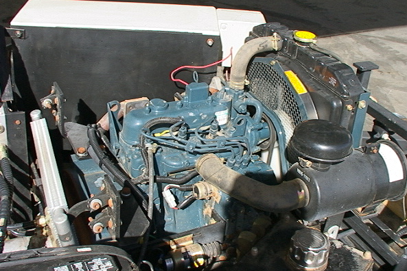
The heart of the system is the 3-cylinder Kubota engine driving the
hydraulic pump(s). The engines radiator is in the foreground of
the image below. Again, things have gotten pretty dirty but there
has been very little use.


Each of the tread rollers has a hydraulic motor on it. Each pair
of these rollers has a linkage and a straingauge sensor.

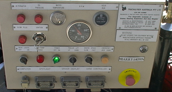
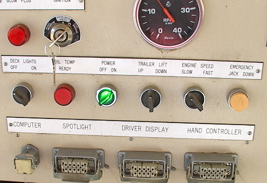
Note that the engine was runing when all these pictures were taken.
See the reading on the tachometer. and the green light.


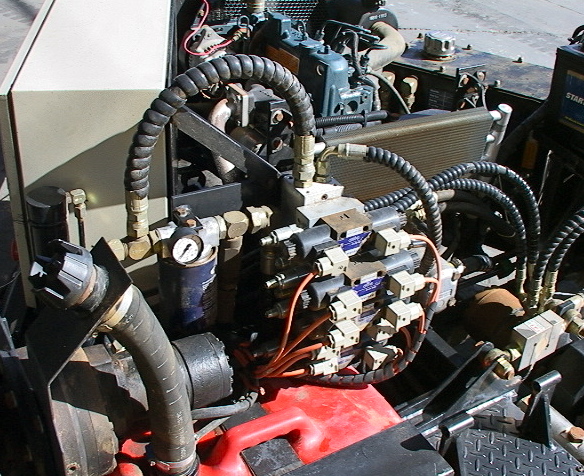
The fuel tank is red in the image above with the filler tube rising to
the left. Behind that is one of the wheel rotation hydraulic motors and
torque amplifying gearboxes. Note all the solenoid valves in the
center of the image. One of the rotational torque load sensors
can be seen in the lower right.


The yellow plate in the middle of the image above is the top of a 5 ton
hydraulic scissors jack.
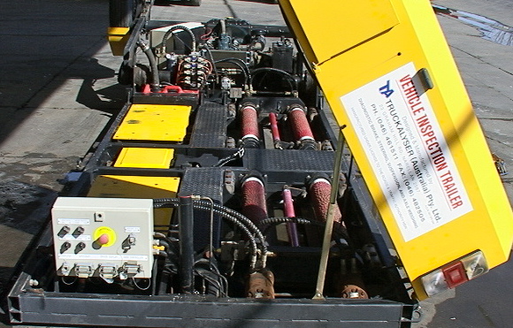

The rear control panel is shown here. again, we don't have
anything that plugs into any of the connectors. A more direct
view of one of the torque linkage strain gauge sensors is shown in the
next image. Note that there are more solenoid valves at the rear.


In the upper right of the image above and in the left of the
image below you can see a pair of the hydraulic motors that couple to
the tire rollers.


The image above shows one of the trailer wheel axle rotation hydraulic
motors and torque hub. The labels are imaged below.


The image below is on one of the hydraulic motors attached to the tire
rollers.

The section of the trailer where the truck drives in is about 6 feet
wide and 112 inches across.


The image below shows the cover for the engine section. As noted,
it could use some sheet metal work before getting attached back in
place.
Additional similar or related items may be available listed separately or on request